The following article appeared in the January, 2022 issue of Hydrocarbon Engineering.
Jeff Bause and Jorge Cadena, NOXCO, USA, explain why ignoring nitrogen oxides and carbon monoxide emissions control systems may be costly to operations.
Emissions control systems are imposed via government regulations, both at local and federal levels. The power industry is no different, as there are regulations in place for a variety of emissions, including nitrogen oxides (NOx) and carbon monoxide (CO).
There are a few ways that these emissions are handled within the industry, but the elephant in the room is that these regulations are getting harder to meet. Not only are regulators looking for lower emissions, but newer combustion turbine technologies actually have higher levels of emissions, particularly NOx.
As such, ignoring an emissions control system is becoming harder to do, and incurs a greater cost. Today, plants should be more proactive regarding the servicing and monitoring of their emissions control systems. Improving these backend operations can have positive financial impacts to the overall operations, potentially resulting in hundreds of thousands of dollars in annual operating profits.
Selective catalytic reduction technology
Selective catalytic reduction (SCR) technology has been utilised for over 30 years within the power industry to treat NOx emissions. The technology uses a catalyst to initiate a reduction reaction utilising ammonia (NH3), typically in an aqueous solution, to convert NOx to nitrogen (N2) and water (H2O).
The reactions typically involved with the reduction of nitrous oxides, made up of both nitrogen oxide (NO) and nitrogen dioxide (NO2), are as follows:
4NO + 4NH3 + O2 ⟶ 2N2 + 3H2O
8NH3 + 6NO2 ⟶ 7N2 + 12H2O
These reactions are affected by operating temperature, oxygen, and ammonia levels. Typically, the temperature range in which these reactions are most prominent is 480 – 750˚F. Below this range, the speed of the reaction slows and other side reactions may become the predominant ones. Above this range, other reactions may occur and, in extreme cases, sintering of the catalyst can take place with irreversible effects on the effectiveness of the catalyst.
The oxygen level should typically be above 8% and below 15%. High oxygen levels can increase the formation of ammonia salts, while lower levels can decrease conversion efficiency. As can be seen in the reactions, there needs to be an equivalent amount of ammonia to that of nitrogen oxide, and approximately 33% more for NO2. Above or below these levels, the reduction reactions shown above may no longer be the predominant ones. Shifts in reaction speed may occur and side reactions may take place – all of which can lead to decreased efficiencies. In some cases, operating outside of these ranges can even result in the creation of NOx.
CO treatment follows a similar approach in that it also uses a catalyst but instead of reduction it employs oxidation to convert the CO to CO2. The primary reaction is as follows:
CO + ½ O2 ⟶ CO2
The CO catalyst uses a different set of substrates and precious metals, typically platinum or palladium, to initiate their reactions. Temperature is again very important for proper conversion and needs to be above 650˚F.
Engineering and inspection
Monitoring the operation of plants is critical. However, more often than not the operators are not paying close attention to the end of the operation: the SCR. It is monitored for alarms, but not necessarily trended for parametric monitoring to ensure its efficient operation. With many variables affecting their operation, parameters should be monitored to avoid unexpected outages and provide the plant payback.
A proper maintenance protocol starts with inspections and monitoring of data. By employing this practice, plants can ensure that their systems are operating within the required envelope of conditions. By performing twice-a year data analysis, a site can determine if changes are affecting their plant operation. The key parameters to monitor are the operating temperature of the catalyst(s), pressure drop, oxygen levels, ammonia flowrate, NOX, and CO levels. Coupling this with annual inspections enables one to anticipate any issues and avoid potentially catastrophic consequences.
Testing is the last component of a robust maintenance programme. A proper testing protocol can help to predict future maintenance needs whether it be a change in operation, maintenance protocol, or replacement of an existing catalyst. A key to testing is ensuring there is a representative sample of the catalyst(s). This requires that several samples from different locations within the catalyst bed(s) be tested. The required number of samples is dependent on the size of the unit, but typically it is recommended that three samples from each side of the catalyst (upstream face and downstream face) be taken. This provides a good distribution and representation of the overall state of the catalyst.
Ammonia injection grid tuning
There are a few aspects of the system operation that can have a major impact on overall plant operations. One of these is ammonia injection grid (AIG) tuning. As shown above, NH3 is required for NOx to be reduced into N2 and H2O. If sufficient NH3 is not supplied, NOX will not be converted at a high level. Conversely, if too much NH3 is injected, one will see elevated NH3 slip, which can result in the formation of NH3 salts (NH3 slip is the quantity of NH3 that passes through or bypasses the catalyst without conversion). Some jurisdictions require that NH3 slip be monitored and maintained below specific permit levels. Slip may occur due to inefficient conversion resulting from temperature profiles that are not ideal, reduced catalyst activity, catalyst fouling, or inefficient ammonia injection.
The first step is to ensure that the system is operating within the ideal range of operating conditions. The next step is to confirm that the system is in good working condition. The distribution of gas through any media is affected by fouling, and the gas tends to go through the path of least resistance. Over time, fouling can take place on the catalyst or within the AIG, which can cause changes in flow patterns. Shifting can also occur with the catalyst due to cycling, which can cause gaps in the catalyst or damaged seals – all of which contribute to bypass and increased NH3 slip.
The SCR control system monitors NOX outlet and is programmed to increase NH3 injection rates to maintain a specific NOX outlet – typically slightly below the permit levels. By injecting more NH3, the system can maximise the reduction of NOX in the regions of the catalyst bed where proper flow is taking place. However, in bypassed areas or regions where velocities may be too high, the NH3 passes through unconverted. In this case, one may meet the NOX emissions and even the NH3 slip requirements, but it could be causing other costly scenarios. For example, a high quantity of NH3, especially in lower temperature regions, can cause the formation of ammonia salts.
2NH3 + SO3 + H2O ⟶ (NH4)2SO4 (ammonium sulfate)
NH3 + SO3 + H2O ⟶ NH4HSO4 (ammonium bisulfate)
These salts can cause fouling on downstream structures, including heat recovery steam generator (HRSG) boiler tubes. Not only can this cause an increase in backpressure, but it can also reduce heat transfer efficiency. This has the effect of decreasing gas turbine power output, increasing heat rate, and reducing steam production in cogeneration applications. This results in greatly reduced profitability of the overall operation.
Additionally, injecting higher levels of NH3 throughout the catalyst causes it to lose activation more quickly. This can have significant capital cost implications to a plant where the catalyst will need to be changed out more frequently, and perhaps even unexpectedly. Stack NH3 compliance is another liability. Many plants have to apply for a variance, but this can be avoided with proper maintenance.
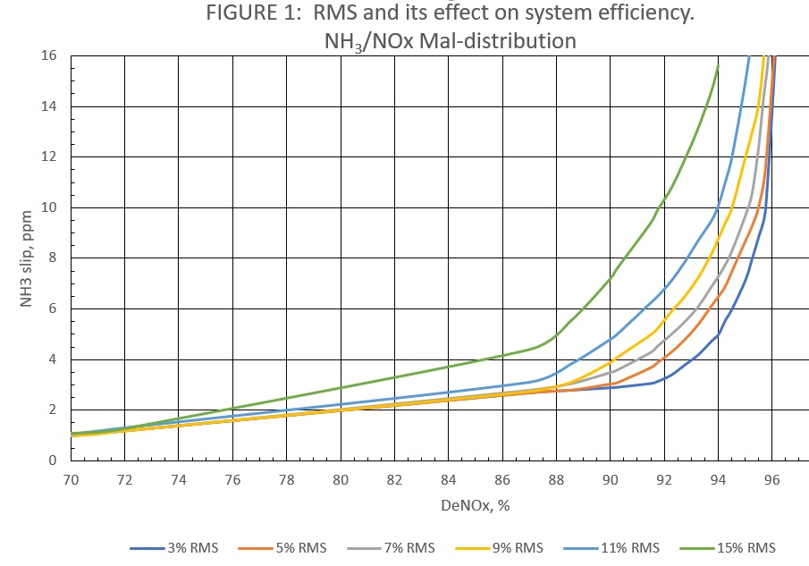
The goal is to provide enough NH3 for proper reaction, but not to have excess passing through sections of the catalyst. Ideally, there will be a uniform NH3 or NOx outlet across the catalyst face. This factor is termed as root mean square (RMS), which ideally should be less than 10%. The lower the RMS, the more uniform the outlet NH3 is across the catalyst bed. This is extremely important as it dictates how effective the complete catalyst volume is being utilised. As shown in Figure 1, with too high an RMS, one cannot achieve high efficiencies within today’s systems. The NH3 slip is indicative that only a percentage of a catalyst is being utilised effectively, which limits the maximum efficiency the system can achieve without tuning.
By performing AIG tuning, the above results can be minimised. Tuning consists of monitoring NOX output across the downstream face of the catalyst bed. This can be performed with either a permanent or temporary testing grid, allowing for many different points to be analysed. These points are monitored to analyse how changes to NH3 injection impact NOX conversion at each sample point. Each SCR design will have different tuning valve and AIG configurations, but by optimising the flow of NH3 to each section of the catalyst bed, the overall amount of NH3 can be minimised.
Case study
Figure 2 shows the results from an AIG tuning on a 501F gas turbine. The client was approaching their permit level on NH3 slip of 10 ppmv. Up to that point, they were content utilising more NH3 as they were not out of compliance. The system was reviewed for plugging of nozzles and any issues with the NH3 injection grid.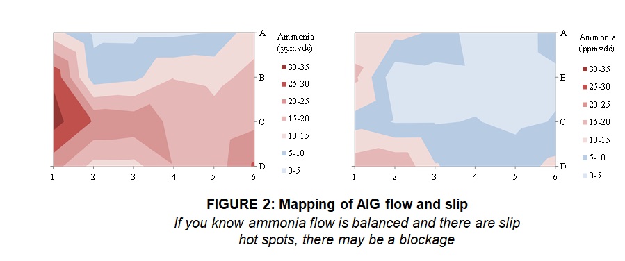
Once the AIG was confirmed to be operating properly, a tuning grid was set up using 24 data points. Initially, significant levels of NH3 were seen across a majority of the catalyst face. After three iterations of tuning, the NH3 slip was decreased to 2.5 ppmv, a quarter of their permit limits. As shown in Figure 2, the amount of NH3 slip became more uniform across the face of the catalyst bed.
The tuning decreased the amount of NH3 injected from 340 lb/hr to 250 lb/hr – a decrease of 26.4%. Based on operating 8000 hr/yr, this ammonia reduction will result in an annual operating savings of US$96 257 (based on an NH3 cost of US$1/gal). This cost savings does not include the labour saved by minimising logistics for shipping the excess NH3.
Catalyst cleaning
Catalyst cleaning is perhaps the simplest way to optimize an SCR in order to realise operational benefits. Fouling of the catalyst can take place for a variety of reasons, including atmospheric conditions, poor quality NH3, insulation damage, and ductwork scaling.
As part of an inspection plan, it is recommended that all of these aspects are monitored in order to avoid potential fouling.
This fouling can result in decreased conversion efficiency and increased pressure drop across the catalyst bed. Some users may see this and change out the catalyst prematurely or derate their operation until the problem can be resolved. Often, the problem is not too severe and many sites continue operating and meeting their emission requirements. However, this is often achieved while operating at a higher pressure drop and/or while injecting extra NH3. The NH3 slip implications have been addressed, but the high backpressure has its additional set of penalties.
Many users will not react to a slow increase in backpressure of 1 – 2 in. of water column (w.c.). However, this can have a huge impact on plant profitability. Cleaning of the catalyst requires an experienced servicer to utilise the proper air pressure to remove particulates fouling the catalyst. Depending on the nature of the fouling and catalyst composition, different pressure requirements may be needed, as this is critical to avoid damaging the washcoat, which contains the active catalyst material.
Medical-grade compressed air is utilised to ensure no additional contaminants are introduced into the catalyst bed. In the case of a CO catalyst, improper cleaning can also cause the transfer of precious metal catalyst to the downstream SCR catalyst. In these situations, this can cause the SCR efficiency to be reduced, and in some cases even result in the formation of NOx.
Case study
Each operation’s approach to cleaning and differential pressure (dP) can have very different impacts. NOXCO’s team was contacted by a client to review SCR operations, and determine the reason for increased pressure drop and why their unit was tripping. The client was operating several gas turbines.
Upon inspection, it was found that there was masking of the SCR catalyst due to insulation liner damage. The liners were repaired and a cleaning of the catalyst took place. Due to plugging, one of the client’s units was operating with a backpressure through the SCR of between 9 – 10 in. w.c. at a reduced operating load.
Upon cleaning, which was performed over a two-day period, the system backpressure was reduced to 2.6 in. w.c. at full load. This reduction in backpressure allowed the client to operate closer to design conditions and run the unit at 175 MW at full load. Over 1 MW of power output was returned to the capacity of the system, as the top end had been limited due to the elevated backpressure. Additionally, the decrease in dP caused an improvement (decrease) in their heat rate. The heat rate improvement was approximately 0.7%, which allowed the plant to realise US$275 000 in fuel savings every year based on 8,000 hours of run time.
While most plants will not have such large dP to overcome, there are still significant savings that can be realised by decreasing dP by 1 – 2 in. It is especially significant when taking into account lost revenues generated by not producing the 1 MW of top-end output.
CONCLUSION
It does not take much in terms of monitoring and maintenance to result in significant savings for a facility. In today’s cogeneration or combined cycle plant designs, the SCR and CO systems are integrated into the HRSG, which highlights another major area for savings. Maintenance of the HRSG, as alluded to earlier, can also have a huge impact on the plant operation. Cleaning of the HRSG tube (HP and LP) can decrease backpressure of the system with financial benefits that exceed that of the SCR cleaning. Additionally, by removing contaminants from the tube surface, the heat transfer efficiency can be improved, resulting in better steam generation. Performing maintenance services regularly can have significant benefits to a site’s profits, operations, and longevity. It is important to seek out a company that specialises in these areas, and can perform work on a scheduled basis and with guaranteed results.
Recent Comments